Portable Humidity, Temperature, Pressure sensor.


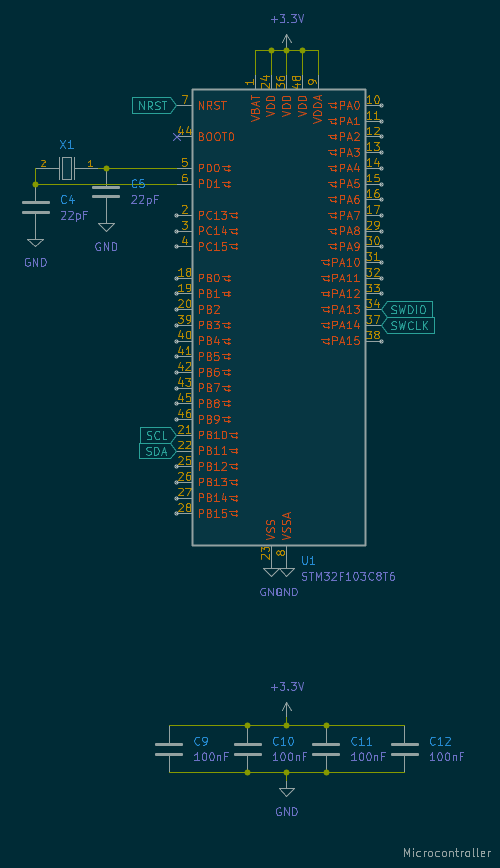
Previously there was a post labeled with "idea" about a small device that can measure humidity, temperature and pressure, and it fits on keychain. The goal of this post is to show the process of making a PCB board for that device. Schematic was easy, considering how it has just a microcontroller, sensor and voltage regulator.
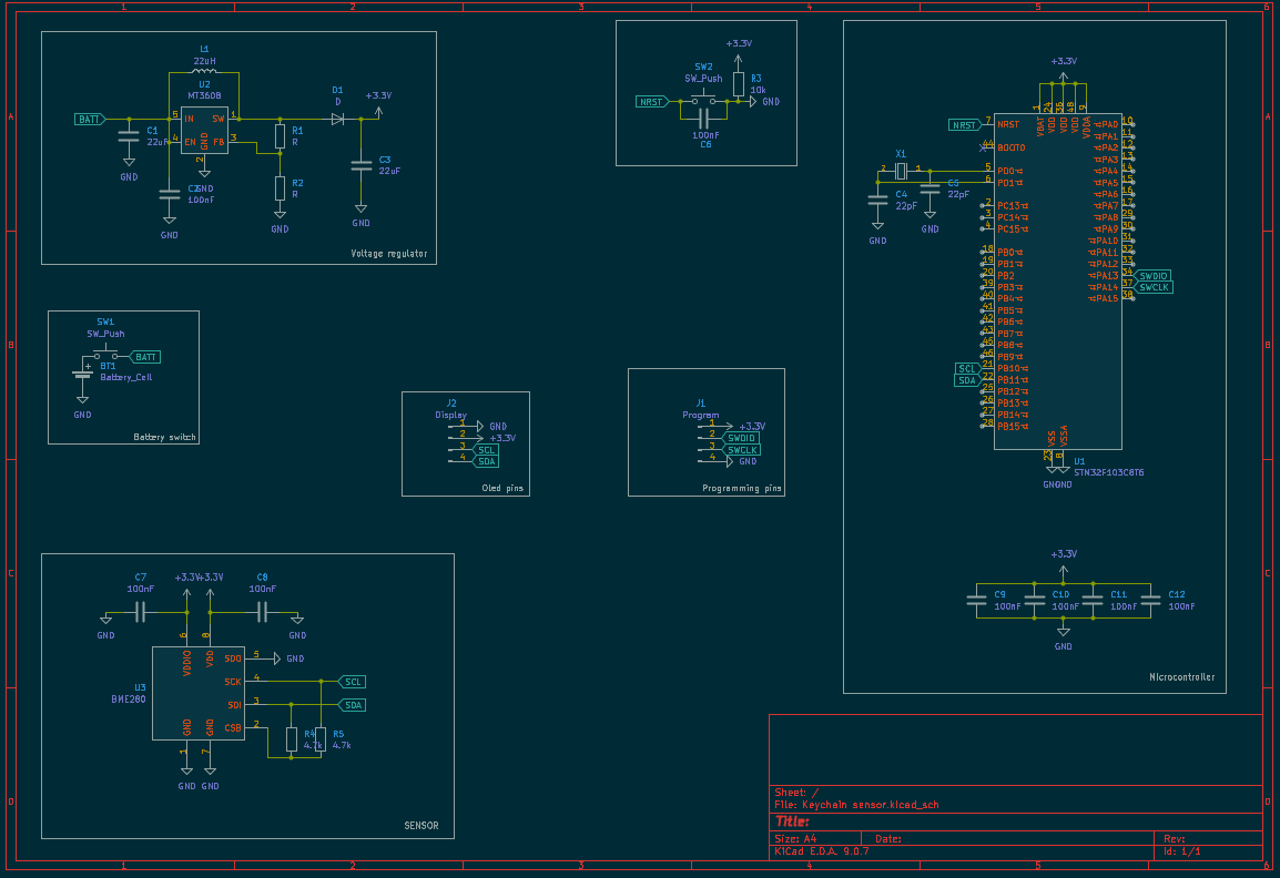
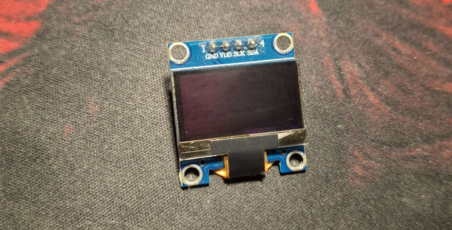
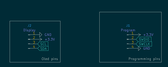
There are also pins for programming and pins for oled display.
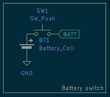
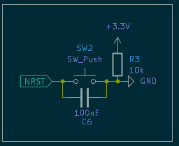
One last minute decision was to implement a button that when pressed the battery is connected.
Why is that?
The device is not supposed to work all the time, and if it does, it will drain the small battery really fast. Now I hope that all those capacitors soke up all the wild spikes in voltage, there is also a 22uH coil that should soke up ampere spikes and dips.
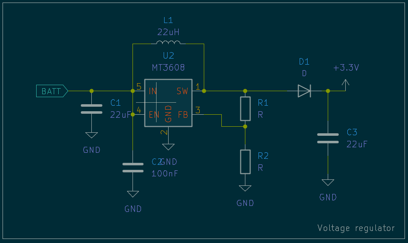
Voltage regulator:
Battery switch:
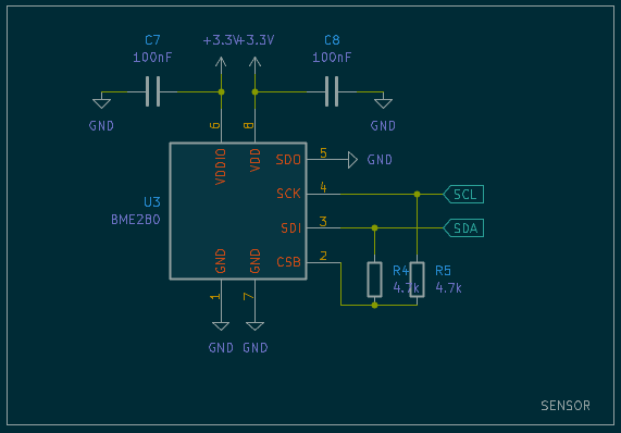
BME280:
Microcontroller(STM32F103):
Now it's time for the dark territory. A place where sun in fact does not touch the land.
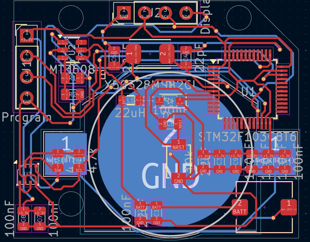
The board is designed so it fits the hole of a 0.96 inch oled display, but overall is wider than display. Here comes the mess of measuring the display.
For some reason on internet is a lot of schematic of those 0.96 displays, but each is different by a few millimeters. How is that possible when they all use the same display? I guess the PCB underneath is a bit wider than display on some boards. But then how the board that I bought in its main schematic it says one value, and when I measure it with caliper, it is different? It's all weird, I did my best to position those holes.
Now the battery holder:
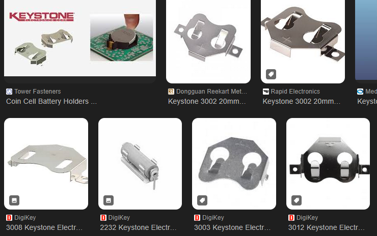
Apparently those coin batteries have standards that are labeled by 4 numbers. The one I used is for CR2032 battery. Those batteries are 3V and have 240mAh in them. The problem was that battery stand uses one layer of PCB, and under the battery I can use only one layer, so position was crucial. No vias under the battery, so sensor, and voltage regulators were placed away from the battery.
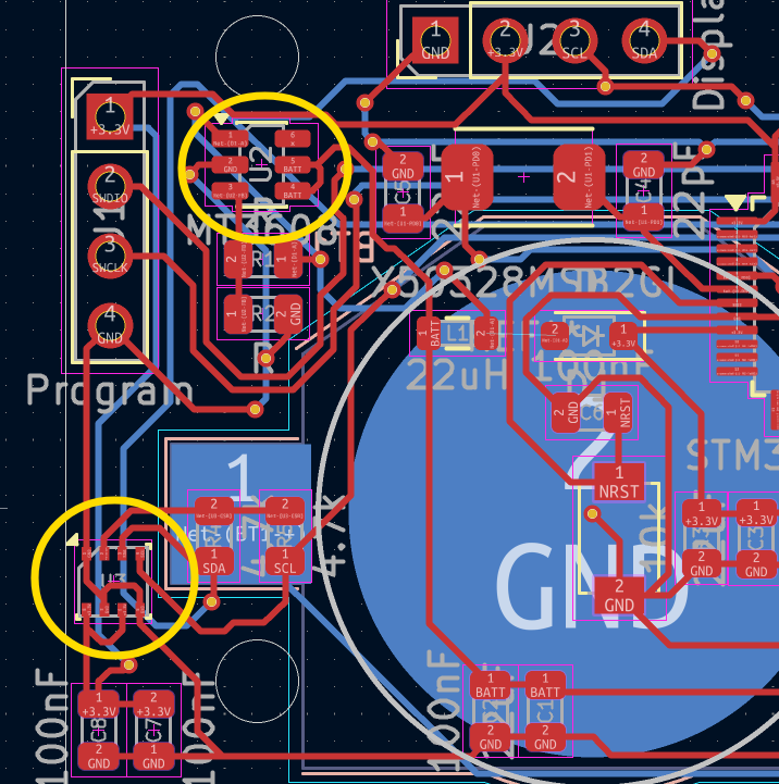
That's why routing is the way it is, but without that constraint it wouldn't be much better.
The sensor was placed to the right side of the PCB so it's exposed more to the air. Later when casing will be designed, that whole side will probably have an opening, or a couple of small openings, so it looks better.
Printing the PCB board:
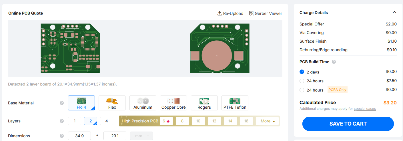
$3.20 for 5 boards.
Shipping is the problem, that's why I'm waiting for more board designs so all of them can be ordered at the same time, and it all goes under one shipping.
As for components
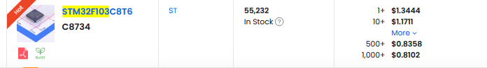
Only expensive component is microcontroller that goes for $1.3.
Other component is battery holder:
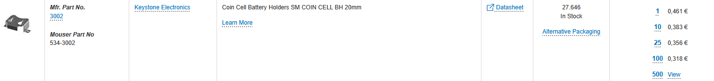
It's 0.461 EUR, and I don't like that. Other than that coin batteries are about 1 EUR, maybe a little more. And that's it for the project. The next post will show fully assembled board and how it works.