PI regulator in code

Goal of the day is understanding the PI regulator. Before anything there is a great resource that explains PI and other regulators in detail and its: controlsystemsacademy.com
t = 0:0.01:10; % Time vector
setpoint = 1.0; % Desired value
Kp = 2.0; % Proportional gain(how strong the P part is)
Ki = 1.0; % Integral gain(how stron the integral part is)
dt = 0.01;
y = zeros(size(t)); % Output
integral = 0; % Integral accumulator
for i = 2:length(t)
e = setpoint - y(i-1);
integral = integral + e * dt; % Accumulate over time
u = Kp * e + Ki * integral; % PI control signal
dy = (-y(i-1) + u) * dt;
y(i) = y(i-1) + dy;
end
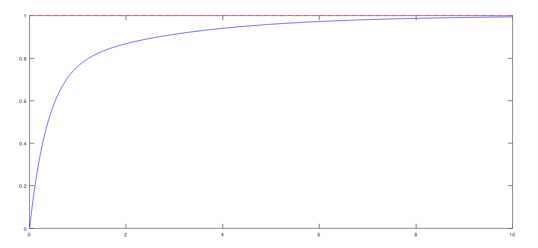
plot(t, y, 'b', t, ones(size(t))*setpoint, 'r--');
xlabel('Time'); ylabel('Output');
grid on;
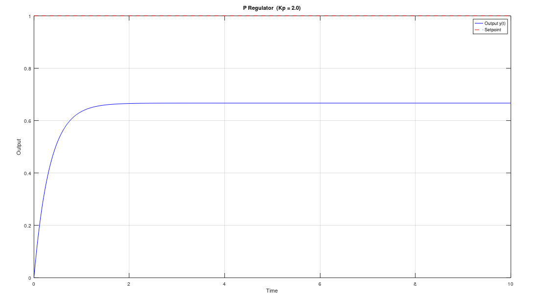
For loop is doing all the work for us here. It does the calculations for proportional part, in other words it's just taking the difference between setpoint and current value and multiplies it by gain. On top of that it adds integral part, or in simpler words. It adds up the area underneath the current value as it rises or falls and sums it up and adds it to the current value. So that way it's actually possible to get to the desired value.
The output looks like this:
PI regulator with disturbance:
t = 0:0.01:10;          % Time vector
setpoint = 1.0;         % Desired value
Kp = 2.0;               % Proportional gain
Ki = 5.0;               % Integral gain
dt = 0.01;
disturbance_time = 5.0; % When disturbance kicks in
disturbance_mag  = 0.5; % Magnitude of disturbance

y = zeros(size(t));     % Output
integral = 0;           % Integral accumulator

for i = 2:length(t)
    e = setpoint - y(i-1);
    integral = integral + e * dt;
    u = Kp * e + Ki * integral;

    % Step disturbance added to the plant input
    d = disturbance_mag * (t(i) >= disturbance_time);

    dy = (-y(i-1) + u + d) * dt;
    y(i) = y(i-1) + dy;
end

plot(t, y, 'b', t, ones(size(t))*setpoint, 'r--');
xline(disturbance_time, 'k:', 'Disturbance', 'LabelVerticalAlignment', 'bottom');
xlabel('Time'); ylabel('Output');
grid on;
Right here at the fifth second a step disturbance is applied, so we can see how it affects the system with PI regulator.
Output:
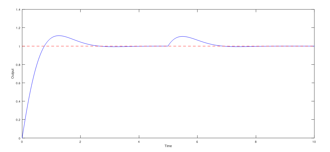
It's possible to see how system gets right back to the setpoint value after the disturbance is applied. As opposed to just proportional regulator which stays on the value of the initial disturbance.
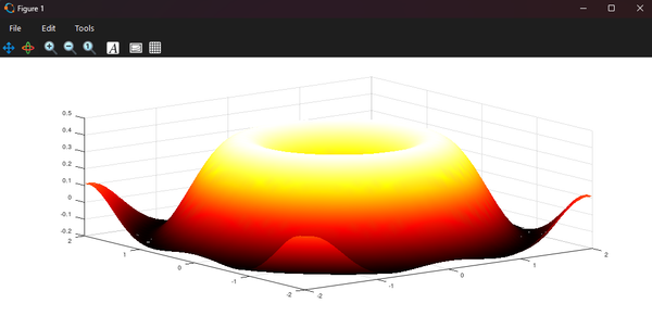
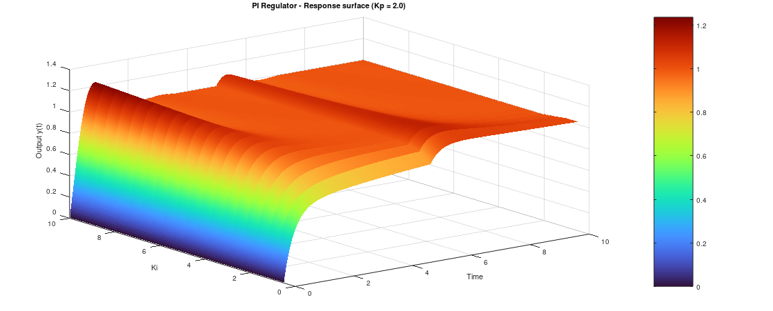
At the end i would like to show what i found on the Internet:

It's a 3D graph showing how response is changing depending on Ki variable changing.
PI regulator is used when just proportional regulator is not enough. It's used in motor speed control, thermal regulation, liquid flow control. It's baffling how important it is and how little i knew about it, and still know. The point of this is trying to understand it to the best of my ability. With code I'm somehow able to understand it easier, but when those math formulas get thrown in the picture, it's easy to just give up on it. But when we think about it, it's not that complicated.