Chess Handheld Console PCB Design

On my blog previously i posted a post labeled as an idea for a handheld gaming console just for playing Chess. The goal was to make a gaming console out of ESP32 S3 which is a microcontroller, so it’s not really suitable for gaming console, but microcontroller as itself has a lot of power.
Long before this post i tried fitting a chess engine in the ESP32 S3, and it worked. The chess engine has to be stripped of it’s advanced features that require a lot of ram, but in spite of that it can perform at an about 2000 chess rating. Basically a 2000 rating bot can fit into ESP32 S3.
However, back in the time when i tried that, i used ESP32 S3 WROOM 1, and later i found there is even more powerful version called (guess what) ESP32 S3 WROOM 2, featuring some kind of AI boost, but more importantly 32Mb of SRAM.
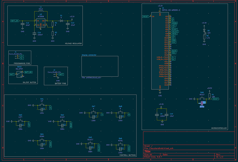
The whole schematic:

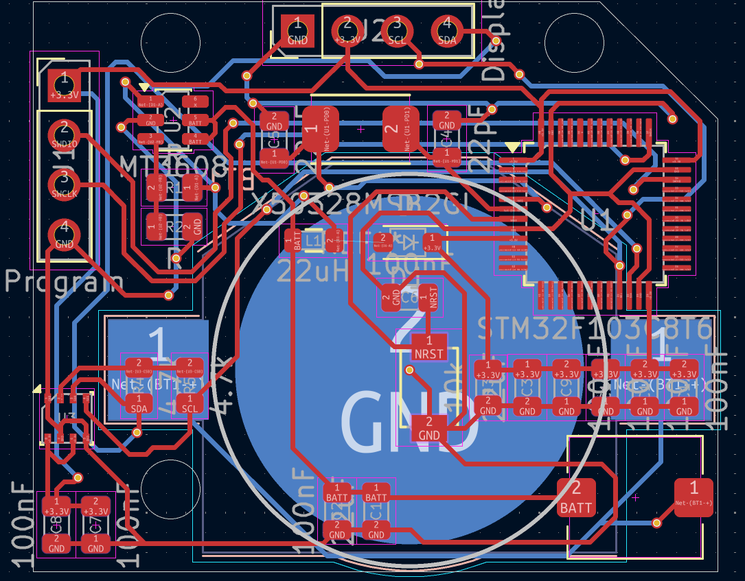
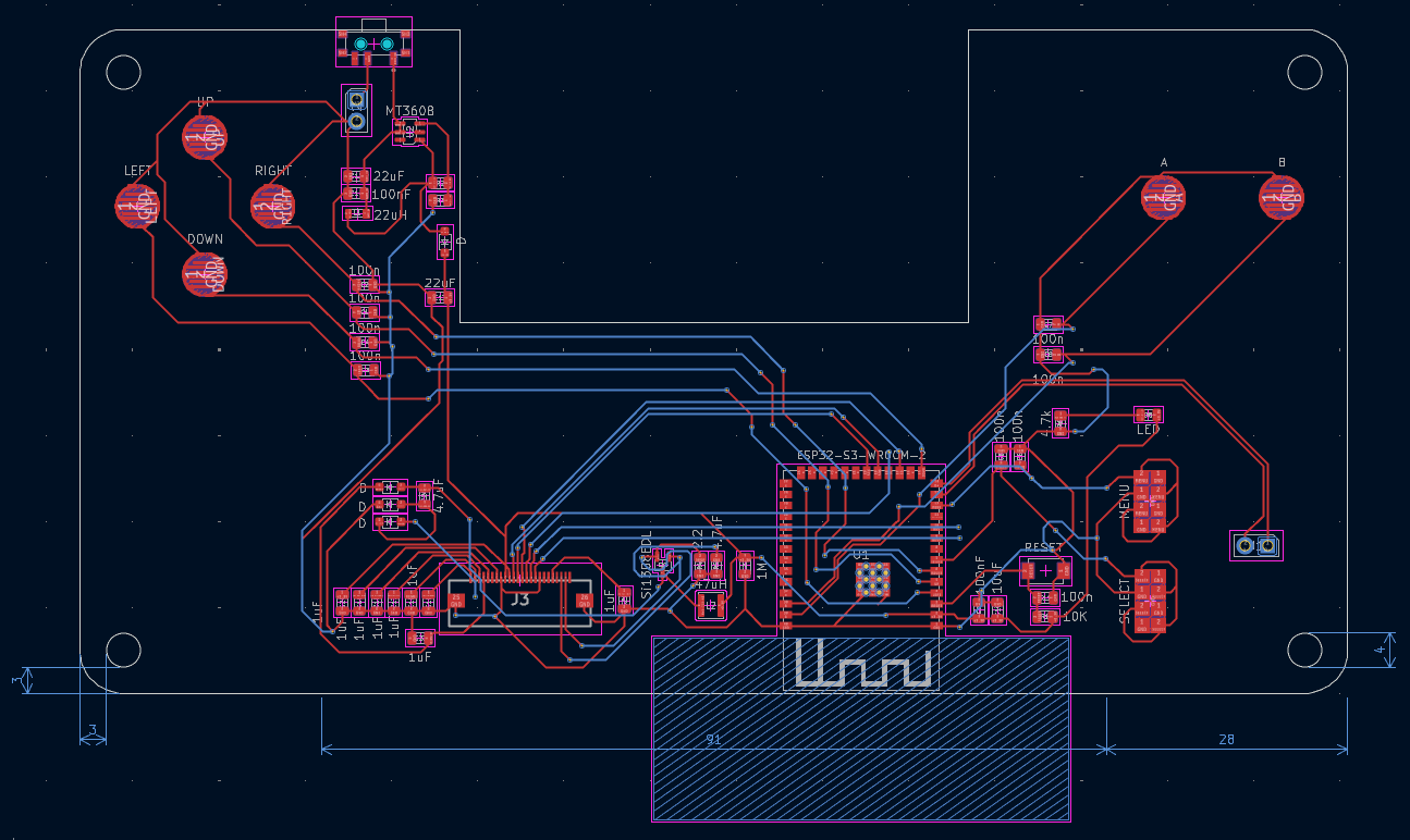
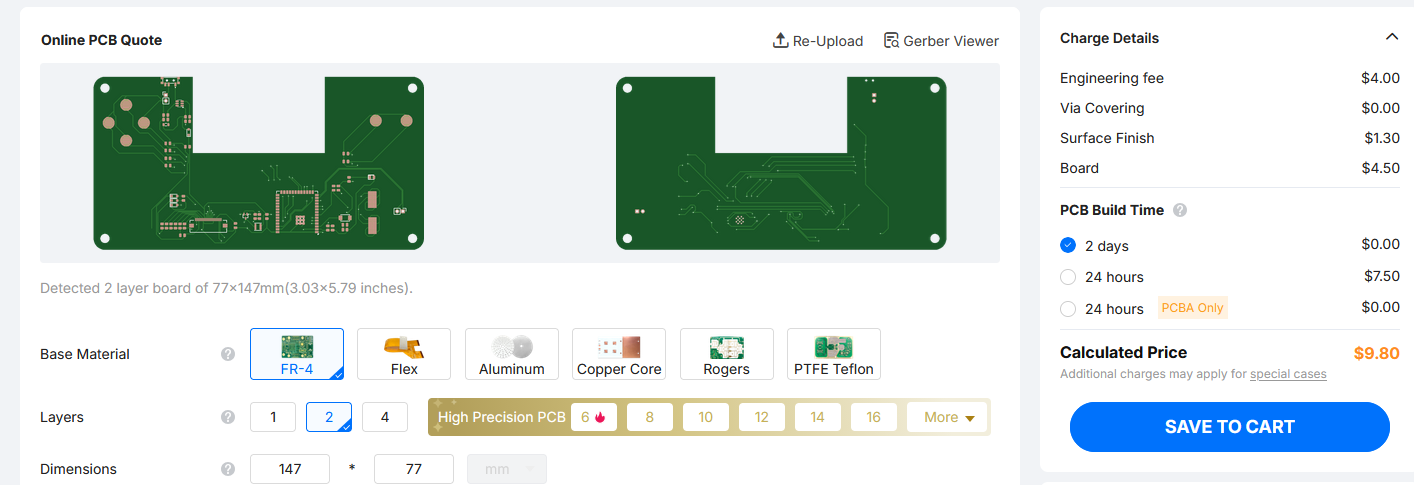
PCB Schematic:

The PCB schematic is dog water as usual, but I'm confident it will work. Great thing with ESP32 is that chip can be interchanged with ESP32 S3 WROOM 1, which is half the price of WROOM 2, in case the goal is making a cheap device.
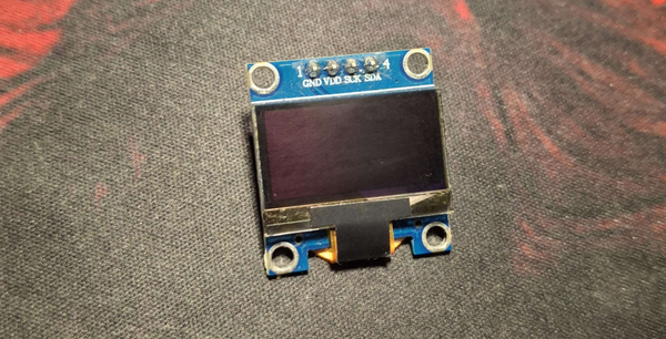
The design of a device is determined by it’s PCB. From PCB schematic we can see that device will be in a style of Nintendo Switch. So the controls will be to the left and right of the display. The display is a 4.2 inch e-paper display. The max refresh rate for it is 0.3 seconds, so the max speed of moving chess peaces on the board is 3 squares in 1 second. I think that’s good if bullet chess is not considered. Because I'm confident people can click the buttons more than 3 times a second, and that would be bad experience if someone has to wait for the display to load.
There is also a problem of processing power. Is ESP32 S3 capable of loading it 3 times seconds? That’s a problem for when PCB is printed and coding starts.
Controls:
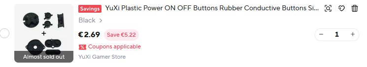
Control buttons are the same as on Gameboy Color. They are available on AliExpress for about 3 EUR.
Reason for that is because i wanted to make a real D-Pad, and Gameboy replacement buttons are widely available. On top of that there is a great footprint library on Github by Nataliethenerd, and it's the footprint for those Gameboy buttons. Those footprints are just basic exposed contact which are connected by a button membrane when button is pressed.
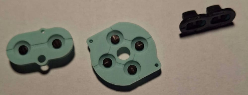
The challenge will be designing a case for those buttons to fit.
For the end, the question is how much will it cost:
And all the components should be about 15 EUR. I still need to say something for the end. I know this is not a full project, so the next post will be when board is printed. Currently, I'm waiting for a couple of PCB designs to pile up so i can order them all at once and pay just one delivery. Considering how every time delivery is about 4x the PCB itself.
That's it, thanks for reading.